Displacement constraint
Applying a displacement constraint to selected elements in a generative design study is part of the Generative Design workflow.
Using displacement constraints
Use a displacement constraint on surfaces that are not fixed, but instead can move during normal operations. A displacement constraint allows the part to move in a specified direction and by a specified distance. It the part exceeds this limit, then it is allowed to deform. Examples of such parts include a bushing, a gasket, or a spring-loaded part such as a push button.
The Generative Design tab→Constraints group→Displacement command  defines by how much and in what direction a surface can move, instead of the default, which is no displacement.
A displacement constraint with a zero value works the same as a fixed constraint.
Displacement in Generative Design works differently than In QY CAD Simulation, where it is treated as a load instead of a constraint. As an FEA load, displacement is applied to the part before starting the analysis, and is therefore used to compute the stresses on the part.
In Generative Design, displacement is applied as an operational requirement to force a part to behave in an expected manner. This ensures that the structural optimization accounts for the resulting deformation.
Displacement constraint inputs
Displacement constraints require the following information:
-
Geometry—You can select one or more faces or features.
-
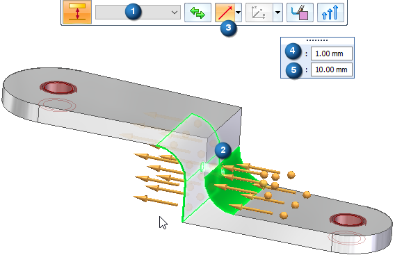
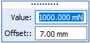
Displacement Direction, Distance Value, and Offset Value—From the Direction Type list on the command bar, choose the method you want to use to specify displacement direction and enter the displacement distance and offset in the dynamic input box:
Note:The Offset value that is displayed as a default is the recommended value based on the volume of the design space and the study quality.
Use this Direction Type
To
And enter values

Along a Vector
Orient the steering wheel primary axis to specify the direction in which the load is to be applied.

Normal to Face
Apply the constraint normal to the selected face. This is the default option. The default direction is out of the face. You can use the Flip button to reverse it.

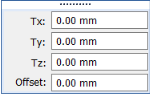
Components
Define constraint direction by specifying the individual X, Y, and Z direction components with respect to a coordinate system.
The default coordinate system is the Base coordinate system.
Type the Tx, Ty, Tz, translation component values.

Select Coordinate System
If a user-defined coordinate system exists in the model, use the Select Coordinate System button and list to activate it.
Editing displacement constraints
The constraint symbols are added to the selected geometry in the design space, and an edit definition handle is shown on the design space body, with a label such as Displacement 1. You can use this handle to edit the inputs that created the constraint.
A corresponding entry is added to the Generative Design pane, under the Constraints node, as Displacement 1.
-
To review the values assigned to the constraint, hover over the label name in the Generative Design pane, or click the label to display the handle on the body.
-
To edit the constraint, double-click the label in the Generative Design pane, or click a displayed handle on the body.
© 2021 UDS